|
||||||
|
||||||
None
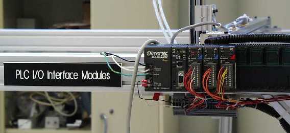
PLC- Programmable Logic Controller
Input (X)- signal from an external source
A PLC consists of three Primary parts. They are the base, the CPU, and the various modules.
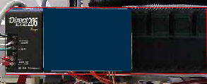
The base unit has many functions. Primarily it is a power supply for the CPU and the modules. It also houses these components in what are called "slots." These slots have connections that make it easy to plug in the modules or remove them. These connections connect the modules to the power supply and to the CPU for communication.
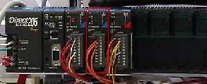
The CPU is what controls the whole routine. It stores and runs the program. It also stores local variables called relays used in the program. The CPU polls the inputs and adjusts the outputs as the program specifies.
Inputs:
Outputs:
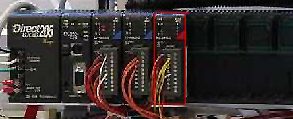
There are many different kinds of modules but we will only refer to simple input and output modules. The input modules are used by the CPU to determine the status of the inputs. Output modules are used to control devices connected to the output signals. Modules are addressed by a code. For our particular PLC the code used is X for inputs and Y for outputs. They also have a number associated with them so they can be referenced. Going from left to right they are numbered like so: X0, X1, X2, X3, X4, X5, X6, X7. The next set would be numbered: X10, X11, X12, X13, X14, X15, X16, X17. This is the case for both inputs and outputs.
PLC Setup
Once you have assembled these components the PLC is connected to the various inputs and outputs in your system. You must also upload a program to the PLC so it knows what to do with the inputs and outputs.
PLC Programming
The type of programming used to program a PLC is called rung ladder logic due to its form using various levels in the program. In each rung commands are given which use inputs and counter relays to
determine the status of outputs and other counter relays. The three basic commands are:
Normally opened contact
Normally closed contact Boolean: = < >
Normally opened contact
A normally opened contact "energizes" or turns on the rung when the input is on. For example in the following: Y2 will turn on when X3 is sensed to be on by the CPU.
Normally closed contact
A normally closed contact works just the opposite of a normally opened contact. In this example: Y2 will go on when X1 is sensed to be off. Boolean Contact A boolean contact compares the value of the input to a chosen value. The contact energizes when the
boolean expression is satiafied. In this example: Y3 will energize when the value of V2000 (all V values are addresses for variables that can be stored in the CPU) is equal to K4903 (all K values are constants). Other Logic Components Timer A timer waits a specified amount of time before it executes a command.
In this example when X1 goes true it starts the timer at the right. It counts in increments of one tenth of a second so the timer above will wait three seconds (notice the K30) to energize the Y0 output. Counter The "counter" simply counts the number of times that a variable or input is switched from off to on.
In this case, every time that "X1" is turned on, the counter, is increased by one. When the number of counts or switches from off to on that "X1" experiences reaches 3, then "CT2" is initialized. When, in this case, the variable "C10" is initialized, the counter is reset to zero. After 3 counts, and "CT2" is initialized, the output, "Y10" is energized. Counter Relay The counter relays are used to store true/false conditions for use later by other rungs. Notice the C10 in the example above. It has been assigned a value by another rung in the program and is used to reset the counter above. Set and Reset Functions When using a counter, counter relay or a timer a set or reset function can be used to set the before mentioned to a particular value or in the case of the reset to the default value.
The "SET" command allows this input to energize an output, and keep it energized even if the input is turned off. The "SET" command also allows you to energize multiple outputs from a single input as shown in the example above, but multiple outputs are not necessary with this function. Once an output is energized with the "SET" command, it will remain on until it is reset.
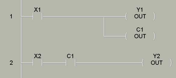
The "RST" function will reset, or turn off the outputs or variables as shown in the example. In the example, when the input "X1" is turned on, the outputs: Y5-Y22 will reset to the off position. End The end command is used to end all programs. Example Program In the example program above X1 will be a sensor that tells the program that there is a board on the conveyor
ready to go. This energizes Y1 telling the arm to mve down and gives C1 a value of true. X2 is a sensor that
tells the program when the gripper is in position to grip. When X2 and C1 are both true the Y2 output will energize closing the grippers.
The program you will run is similar in structure to this small example. It will actuate the robot arm to move a board from the conveyor belt to the oven. |
||||||
On-Line:
|
Net-Control:
|
|||||
|
||||||
|
||||||
|
||||||
|
||||||
|
|
|||||
|
||||||
|
|
|||||
|
||||||
|
||||||
|
||||||
You
can now take the on-line quiz. The results of this quiz will be automatically forwarded to an EAAL TA. In addition, you will receive immediate notification of your correct and incorrect responses for the mutiple choice
questions. The narrative questions will be evaluated by the TA and the response returned to you by EMAIL. You are free to perform this lab again if you are not yet prepared for the on-line quiz.
|
||||||