version: 2010
12-volt Water
Electrolysis Unit
 This document describes my construction
of a compact, high-throughput water electrolysis unit. I do electrochemical
research for my work, so it was fun to "homebrew" something like this. Even so, building this thing was not a light undertaking: it required more skill and
patience than I originally anticipated.
This document describes my construction
of a compact, high-throughput water electrolysis unit. I do electrochemical
research for my work, so it was fun to "homebrew" something like this. Even so, building this thing was not a light undertaking: it required more skill and
patience than I originally anticipated.
A note on safety and the
use of this information:
I prefer that you not share this document with other people without my permission. This is to achieve a modicum of access control, as I intend that people email me (dean_wheeler@byu.edu)
and give me some kind of inkling that they know what they are
doing and will not be endangering themselves and others with this
information. Then I will with this document or a link. I know
this can be annoying to the impatient, but I just don't want anyone to get hurt. So
please use common sense and don't assume accidents will never
happen to you, and follow the safety practices I describe at a minimum. Nevertheless, if
you construct any devices based on the information here, or share the information with others, you alone are
liable for any harm this may cause. The device described
here has the capability if used improperly to seriously injure
people and damage property. And if you are under age 18, do not
use this information.
Most of this document describes my early design, circa 2000. Pay attention to the end of this document where I discuss some of the lessons learned and changes I made to a subsequent design.
In general, I will simply describe my knowledge pertaining to
the operation of this device and how I constructed it. If the
reader chooses to construct a similar device it can be adapted to
the tools and materials available, within the constraints of
safety. The materials I use for the electrodes and electrolyte
are similar to those used in commercial electrolysis cells.
However, my cell is of course much smaller than the industrial
units, runs at lower temperature, and does not collect the gases
separately. This last fact requires an extra measure of caution
in operating my unit: while hydrogen and oxygen gases when mixed
are stable at room temperature, they can explode if heated by a
spark or flame.
Some Electrochemical Fundamentals
I think it's important to have a rudimentary understanding of a few
electrochemical principles. Knowing these things allowed me minimize the amount of trial and error necessary to produce a
functional electrolysis unit.
In its most basic sense, an electrochemical cell is composed
of two electrodes with liquid electrolyte in-between.
Separate chemical reactions take place on each electrode
that depend on the passage of electrical current from one electrode to the other. Technically speaking, a "battery" is more than one cell put together in a single package, but in common usage it can be made of a single electrochemical cell. My electrolysis unit is composed of four cells in series (end-to-end), so that the cell voltages add, and the same current flows through each cell.
In electrolysis of water, hydrogen (H2) gas is generated at
the negative electrode (called the cathode) while oxygen (O2)
gas is generated at the positive electrode (the anode). The
respective electrode reactions in alkaline solutions are:
4H2O + 4 e- ---> 2H2
+ 4OH-
4OH- ---> 2H2O + O2
+ 4e-
This means overall it takes 2 water molecules to make 2
hydrogen and 1 oxygen gas molecules. This requires the passage of
4 electrons through an external circuit (the power source).
While technically the only chemical reactant needed in all
this is water, it is necessary that the electrolyte be composed
of more than just water to promote its electrical conductivity, otherwise an undo amount of energy is wasted as heat in trying to drive ionic current through the electrolyte.
Also the choice of electrode material is important as this
determines the ease with which the reactions are catalyzed and
the service life of the device. Typically, the rate of reaction
is measured as current density, such as the number of amps per
square centimeter of electrode surface area.
Let us propose to run an electrolysis cell that is composed of
two parallel sheets of nickel metal separated by a constant 0.9-cm gap.
In the gap is an electrolyte of 10 wt% NaOH in water. Let's
attempt to operate the cell at 25 oC, atmospheric pressure, and with a current density of 0.15 amp/cm2.
The total voltage required is composed of two parts:
V = ER
+ EIR
ER is the "reversible" or equilibrium voltage of the decomposition reaction
and is 1.23 V. This is the bare minimum voltage you need across a single cell to get the thing to produce any gas at all. EIR
is the "irreversible" voltage or "overpotential" and is the price you pay for being impatient. Electric potential is required to drive the reactions at the electrodes and push ions through the electrolyte. It's like an internal resistance in the cell. The higher the current density you try to run the cell at, the higher the overpotential will be. For our particular example, the overpotential is about 2.2 V after all the complexities are taken into account. Keep in mind that most of this energy is going into heat. In a sense it is wasted energy, but again it is the price you pay for running the cell at a particular current. There are several ways to reduce these losses, but for our purposes the most effective one would be to use larger electrode surfaces so that the current density is lower. This would allow less voltage across the cell to generate the same total current (amps), at the cost of having a physically larger cell.
Sticking to our stated conditions, we see that 3.4 V is required to run the cell. In actuality, because of the heat realeased during operation, the solution will tend
to warm up, and the higher temperatures will tend to reduce the overpotential and thus let the cell run more efficiently. Also, if the electrode surface area is increased due to a rough finish, this will
improve things. On the other hand, the cell will demand more voltage if we attempt to produce gas at elevated
pressures, use a less
concentrated electrolyte, or produce so much froth in the
electrolyte that the bubbles act as a significant insulating
barrier to current flow.
What happens if the voltage is
applied at a level higher than the 3.4 V we calculated? The
reactions will run a bit faster, of course. However, there are
limits to how much current you can push through a cell. Moreover,
undesirable side reactions will also run faster at higher applied
voltages. These side reactions generally will destroy your
electrodes and engage in weird chemistries that could be dangerous. The problem is mitigated if the electrolyte is at very low concentration (nearly pure water) since in this case most of the voltage will go to the ohmic voltage drop rather than the reactions. Nevertheless, I recommend that you
never run an electrolysis cell above 3.5 V. If your cells are
designed and sized properly, you should get 0.1-0.2 amp/cm2
current density from your cell at a cell voltage of 3 V.
Materials
of construction
Electrodes
As stated before, the electrodes need to be of a material that
will allow the respective reactions to proceed quickly with
minimal overpotential (electrical encouragement). From
what I have read, standard commerial electrolysis units use either nickel or
steel for the hydrogen-producing positive eletrode and use nickel for the
oxygen-producing negative electrode. For this reason I used nickel-plated
steel for all the electrodes on my prototype (now defunct)
electrolysis unit. The electrodes worked wonderfully, but the
exterior container had problems, and I decided I wanted
somewhat greater throughput. For my second-generation unit, I use
all stainless steel electrodes, also with good success. I think
that commercial operations prefer nickel for its slightly better
efficiencies and longer service life (it is more corrosion
resistant), but obviously it is harder to obtain for the average
person unless your cousin works at a metal-plating shop.
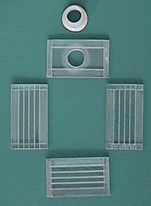
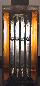
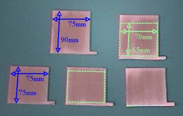 All my electrodes are stainless-steel
plates. I made five plates, 1.5mm thick, cut as shown in the
picture using a band saw. Notice that two of them are taller than
the other three--they will form part of the exterior walls, as
will be explained later. Notice the small extensions on the lower-right
corner of each plate. These tabs are designed to protrude through
the protective enclosure of the electrolysis unit to allow for
electrical contacts. I roughened all the surfaces with emory
cloth, giving them a grain in the vertical direction, so they
would have higher surface area but still be able to shed bubbles
effectively. This also had the benefit of cleaning off any
undesirable oxides accumulated on the surfaces. In fact, it is
important to make sure all surface impurities and organic
contaminants are removed through abrasion and scrubbing with soap
and water.
All my electrodes are stainless-steel
plates. I made five plates, 1.5mm thick, cut as shown in the
picture using a band saw. Notice that two of them are taller than
the other three--they will form part of the exterior walls, as
will be explained later. Notice the small extensions on the lower-right
corner of each plate. These tabs are designed to protrude through
the protective enclosure of the electrolysis unit to allow for
electrical contacts. I roughened all the surfaces with emory
cloth, giving them a grain in the vertical direction, so they
would have higher surface area but still be able to shed bubbles
effectively. This also had the benefit of cleaning off any
undesirable oxides accumulated on the surfaces. In fact, it is
important to make sure all surface impurities and organic
contaminants are removed through abrasion and scrubbing with soap
and water.
The areas of the plates in the picture outlined with dotted
green lines are the final working areas of the electrodes after
the unit has been assembled, and amount to 45.5cm2 on
each plate. The regions outside the dotted green rectangle will
be covered with epoxy. Based on those working areas I estimated
my unit would draw 8 to 10 amps current. It is important that the
power supply or battery that is intended to run this thing be
capable of delivering the required voltage (12v) at that current
level. I use a small sealed lead acid battery (7amp-hr, purchased
online for US$25), which can deliver this current without
straining too much. Fortunately, if the electrodes end up being
oversized in terms of current flow after the unit is
finished, this can be easily remedied by putting less electrolyte
in (so that electrolyte doesn't contact the full surface area of
the electrodes), or by lowering the concentration of electrolyte
(so that ohmic losses are greater). Of the two options the latter
is safer, because less electrolyte means more gas space within
the unit. This gas mixture of hydrogen and oxygen is explosive,
so the less of it in the unit the better.
If stainless steel plate and a band saw to cut it are not
available, other options for electrodes include using thin
stainless-steel sheet cut from the side of metal containers. However, do NOT use any metals for the electrodes
other than nickel or steel or possibly chrome. Aluminum and
copper-containing alloys are not acceptable because they will corrode. A few other exotic
metals such as cobalt are acceptable, but are not readily
available anyway. Technically, carbon electrodes will work, however they tend to flake and erode under the vigorous bubbling action.
It is preferable to use only one kind of metal
for all the electrodes, to eliminate the possibility for
unintended reactions when the unit is not in use.
Electrolyte
Industrial electrolysis units use either highly concentrated
KOH or NaOH. The reason is you need a high-conductivity
electrolyte solution. But you also don't want the electrolyte to
corrode the electrodes. Steel and nickel survive much better in
alkaline solutions than acidic ones. In fact, steel will corrode
less in strong alkaline solutions than in pure water, due to the
formation of a dense protective oxide film on the surface. (Standard
rust is also an oxide film, but it is not so dense). I do not recommend using
substances other than relatively pure KOH or NaOH to make the
electrolyte. For instance, if you use common table salt (NaCl) in
water, when you run your cell your anode could potentially produce poisonous chlorine gas rather than oxygen. Furthermore, the chlorine in solution makes the steel electrodes corrode like crazy. I hope you get the
idea that common household stuff can do unexpected stuff and even be dangerous when put in an
electrochemical environment.
I purchased NaOH ("lye") in pellet form at the
hardware store (it is used as a drain-opening agent). This is
nasty stuff--wear eye protection and rubber gloves when working with it.
After all, it is used to dissolve hair, grease, and the like in
your drain, so it will chew up your bare skin in a short time. A caustic or alkaline solution feels "slippery"
to the touch because it turns your skin oils into soap (saponification),
so if you ever get that slippery feeling, rapidly rinse it off.
Even though my unit requires only 85mL of electrolyte, I made
up a 1-liter batch of 10 wt% NaOH in water, so that I wouldn't
need to be constantly making smaller batches. For those with a chemistry background, 10 wt% is around 2.5
molar. Always add the pellets to the water and not vice-versa. Do
not add the pellets all at once: the dissolving process
releases heat and you don't want the solution to get too hot.
I store the solution in a HDPE plastic container with a screw-tight
lid, and with a warning label. It is better to use distilled water in the mixture (available
in the 'bottled water' section at the grocery store) because the impurities in tap water may decrease
performance of the electrolysis.
Other materials
You must choose inert construction materials for the
electrolysis unit that can survive in a caustic environment, with
joints that can maintain a water- and air-tight seal in spite of thermal expansion, and are
tough enough to withstand possible internal pressure and bumps
and jolts to the unit without cracking. Even with the right materials, it still requires considerable skill and patience to build a container for the electrodes that meets these requirements.
The following materials are suitable for operation in contact
with a caustic solution at or slightly above room temperature.
- HDPE (high-density polyethylene)
- acrylic/acrylate (lucite, plexiglas)
- epoxy
- polyurethane
- polypropylene
- vinyl and PVC
- teflon
- nylon (can be damaged by long-term exposure)
- rubber (ordinary and neoprene)
- carbon
- steel
- nickel
I used plexiglas (acrylate), HDPE, and epoxy in my design. I
recommend the use of a high-quality epoxy or a solvent-based glue.
Materials which are not suitable for caustic service
include:
- plate glass and fiberglass
- PET (PETE) and other polyesters
- polyvinylidene chloride (saran)
- silicone
- LDPE
- aluminum
- copper
Do not assume a material is suitable just because it is not on this list!
Cell configuration
Generic cell-stack designs
Now, some words about cell configuration. We want to put all
our cells into a single container, since this is more convenient
than trying to make several identical, but physically separate
cells. Recall that a cell is composed of two electrode surfaces
separated by electrolyte. The voltage across each cell, as stated
above, should be about 3v. If our power source put out 3v then
we could arrange a bunch of cells in parallel like this:
__________________________
where the red and green lines are the electrode
plates in the electrolyte. Generally, however, we want to put our
cells in series so we can use higher voltages and lower currents
to get the same production rate. A naive attempt at a series
configuration might be:

However, the current will take the path of least
resistance and bypass the electrodes in the center, rendering
them inert. Our stack of electrodes is effectively only a single
cell, and applying a large voltage across this single cell would
be a waste, if not detrimental. The solution is to eliminate the electrolyte path
that allows the "shunt" current to take place:
This improved series configuration is called a bipolar
stack because the plates in the middle are bipolar, each
with one side acting as anode and the other side acting as
cathode. This is the cell configuration I use in my unit.
Note that very small amounts of electrolyte fluid contact
between the cells are acceptable, as the amount of current that
will leak through is proportionately small. And in fact, the
leaks may be desirable in equilizing the electrolyte fluid levels
between cells. (Of course, we do not want any electrolyte to leak
out of the exterior enclosure.) The alternative, if any leaks are
not sufficient to equalize the fluid levels, is to do it by
tipping the unit (with the cap on, so electrolyte does not spill
out).
Note that with the plates arranged as above, it
is possible to power the electrolysis unit with other than 12v,
provide there are electrical connections to the interior plates,
such as
The problem of froth
We want the electrodes to be close together to
reduce the voltage penalty of the electrolyte. However, if
the electrodes are too close, the gas generated on the electrodes
will push too much liquid out the top of the cells as foam/froth. This is just like a opening a shaken bottle of soda pop.
In the extreme case, the froth from the different cells will come
in contact and cause undesirable shunt currents, and the froth
can possibly get pushed out of the gas outlet at the top of the
electrolysis unit. This froth-effect can be reduced by rendering
inert the upper portion of the electrode plates. This keeps the
cells isolated from each other in this region while at the same
time does not contribute further to the amount of gas generated.
I accomplished this by gluing a strip of plexiglas along the top
of each of the interior plates and also by painting epoxy along a
narrow upper portion of all the plates, using masking tape to
keep the epoxy confined to where I wanted it. This modification
to the bare electrodes was performed prior to final unit assembly.
In retrospect, though, this "masking" step on the top of the electrodes is probably unnecessary as long as you don't fill the electrolyte up to the top of the plates. In other words, plan on the electrolyte volume expanding considerably once the cell gets going (see video below). You want the frothy liquid level to just reach the top of the plates. This can take some adjustment to find the proper level.
Also, if the unit is run at several psi of
positive pressure (created by making the gas outlet from the unit
somewhat constricted), this will reduce gas bubble sizes and thus
reduce the amount of froth. I tried to accomplish this by putting a
small wad of cotton in the outlet line where it attaches to the
cap, however I doubt this did much. Anyway, the cotton has the additional advantage of partially
filtering out the micro-droplets of electrolyte that are
inevitably suspended in the gas leaving the electrolysis unit.
Constructing the unit
Enclosure design
(What follows is a description of my 2nd generation unit. At the end of this document you will see that I would do a few things differently if/when I make a third generation unit.)
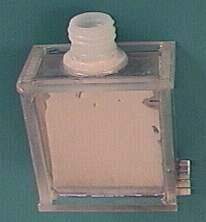
If you think of the enclosure to my unit as a rectangular
solid shape, it has six outside surfaces. The two outside (larger)
electrode plates serve as two of those surfaces; the remaining
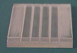
four surfaces are made of 6mm-thick plexiglas (acrylic) pieces
each cut to dimensions 88mm x 52mm. In addition, there is a screw-top
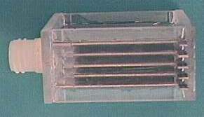
and cap (from a shampoo bottle) made of HDPE. Grooves--1mm deep
and 1.5mm wide--are cut into the plexiglas pieces lengthwise. The
grooves are spaced 7.5mm apart (on center). The metal electrode
plates fit into the grooves, thus ensuring a uniform 6mm gap
between electrode plates, after taking into account the plate
thickness. The interelectrode gap distance could have been
increased to as much as 10mm with satisfactory results. Also, the
four plexiglas pieces have 1-mm-depth rabit cuts on the ends to
allow better joints between them. (I realize that the rabit cuts
are only needed on the ends of the top and bottom pieces rather
than on all four pieces, but I got a bit overzealous while
cutting them.)
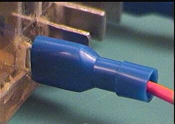
You may notice that all five of my electrodes have tabs which
protrude outside the enclosure. I did this so I could measure the
voltage difference between each pair of adjacent plates to make
sure each cell in the unit was running fine. However, this
introduced additional complication into the design--tabs on only
the outside two plates are necessary. Notice the vertical slots
along the bottom edge of one of the plexiglas side-pieces to
allow the metal connection tabs to stick out of the enclosure.
The tabs are about 6mm tall and 14mm long, and permit a female
quarter-inch electrical coupler to be attached.
A few words on epoxy-craft
 Everything was glued together with epoxy.
I use a high-quality low-volatility marine-grade epoxy that comes
in quart sizes. One of my complaints about the small two-barrel-syringe-applicator
epoxies available in all the hardware and autoparts stores is
that these epoxies are usually quite thick/viscous. This makes
them convenient to work with in most applications, but wouldn't
have worked as well here. I needed the epoxy to be able to
penetrate into cracks well and to form strong, airtight bonds. I
find that when I mix the two components of those thick viscous
epoxies a lot of bubbles get permanently trapped in the mixture,
and I felt that would compromise this design. This enclosure has
to keep a highly caustic solution contained under somewhat
positive internal pressure, with zero gas or liquid leaks.
Frankly, this is the toughest part of building this electrolysis
unit. I found that the areas most likely to have leaks were the
corners where three pieces are coming together in one place.
Everything was glued together with epoxy.
I use a high-quality low-volatility marine-grade epoxy that comes
in quart sizes. One of my complaints about the small two-barrel-syringe-applicator
epoxies available in all the hardware and autoparts stores is
that these epoxies are usually quite thick/viscous. This makes
them convenient to work with in most applications, but wouldn't
have worked as well here. I needed the epoxy to be able to
penetrate into cracks well and to form strong, airtight bonds. I
find that when I mix the two components of those thick viscous
epoxies a lot of bubbles get permanently trapped in the mixture,
and I felt that would compromise this design. This enclosure has
to keep a highly caustic solution contained under somewhat
positive internal pressure, with zero gas or liquid leaks.
Frankly, this is the toughest part of building this electrolysis
unit. I found that the areas most likely to have leaks were the
corners where three pieces are coming together in one place.
I also believe that the epoxy I use has higher chemical
resistance than the generic hardware-store type. I purchased mine at TAP Plastics (a company with a few store locations on the U.S. west coast) for US$25 for 1.25 quarts (total
volume of both components). Marine supply stores might also be a
good source of epoxy since fiberglassing with epoxy is
extensively used in boatbuilding. I use two well-cleaned-out (with
acetone) liquid-hand-soap pump dispensers to dispense the two
components for making small batches. It is also nice to have a
supply of latex gloves on hand to wear while working with the
stuff.
 My epoxy has a 15-30 minute pot life (if
it is thinly spread it takes longer to harden due to more heat
dissipation). After mixing the epoxy, I placed it into a 10cc
syringe fitted with a fine plastic tip. This was invaluable in
allowing me to squirt the epoxy where I wanted (in the grooves,
for instance) without dripping it all over the place and making a
mess of things. If the epoxy were to have dripped all over the
electrode plates while I was installing them, this would have
created inert spots where no reaction could take place. In order
to preserve the syringe, I immediately clean it out with acetone
before the epoxy has hardened inside.
My epoxy has a 15-30 minute pot life (if
it is thinly spread it takes longer to harden due to more heat
dissipation). After mixing the epoxy, I placed it into a 10cc
syringe fitted with a fine plastic tip. This was invaluable in
allowing me to squirt the epoxy where I wanted (in the grooves,
for instance) without dripping it all over the place and making a
mess of things. If the epoxy were to have dripped all over the
electrode plates while I was installing them, this would have
created inert spots where no reaction could take place. In order
to preserve the syringe, I immediately clean it out with acetone
before the epoxy has hardened inside.
Once all the parts were made, the
construction went something like this:
- Sand all portions of plexiglas that will or are likely to
be in contact with the glue. Technically all that is
required for a good bond is an extremely clean surface,
and this is easy to achieve by sanding which exposes
fresh surface.
- Assemble all the pieces without glue to make sure
everything fits together properly.
- Get the metal plates successfully secured into the two
plexiglas side-pieces and the bottom-piece. Try to make
reasonably airtight metal-plexiglas and plexiglas-plexiglas
bonds, particularly where the electrical-connection tabs
protrude through the plexiglas side-piece.
- Glue the screw-top onto the plexiglas top-piece. Do not
yet glue the top-piece onto the rest of the assembly.
- Using the syringe, direct epoxy into the bottom of the
four "deep narrow wells" formed by the the five
metal plates and side/bottom plexiglas pieces. I put
enough to make the epoxy a few millimeters deep. This
decreases the likelihood of any leaks at the bottom of
the cells, particularly where the tabs stick through the
enclosure and the plexiglas pieces are joined together.
- Finally, glue the plexiglas top-piece with screw-top onto
the rest of the enclosure.
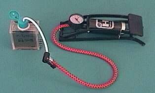
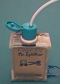
- After the epoxy has cured for another day, do a leak test
by pressurizing the unit with several psi of air (see
picture of example of how I connected a bicycle pump to
the unit) and immersing the unit in water. I found that I
had two leaks: one at a top corner and another at the
bottom where a tab was.
- Eliminate those leaks! I tilted the unit so that the area
of the offending leak was at the lowest point, then put
the tip of the syringe through the hole in the screw-top
and applied epoxy as close as I could to the leak. Within
a few seconds the epoxy ran down to this 'lowest point'.
I then put the cap on the unit and pressurized the unit
to about 15psi to force the epoxy into the leaky crevice.
Then I let the epoxy harden with the unit still tipped so
the leak was at the lowest point.
Some
Final notes
Rigorous pressure testing
and safety
Before I even considered putting caustic electrolyte in my
soon-to-be-finished cell I wanted to be sure it could hold air to
a reasonably high pressure. After the leakproofing in step 9
above, I pressure tested my unit to 50psi and found no leaks (I
could have gone higher, but didn't want to push my luck). Even
with that margin of safety, I keep the unit inside a secondary
container--a smallish plastic 'tupperware' box--while it is busy
electrolyzing, in case a leak or more serious problem were to
develop. I don't want concentrated NaOH going all over the place.
period. It is also a good idea to keep a bottle of water nearby
whenever operating the unit, so that in case of an emergency you
have a means of washing the NaOH off. I always wear safety
glasses when I approach the operating unit. I also don't use the
unit for long-term storage of electrolyte: after I have finished
using the unit for the day, I transfer the electrolyte back into
another container and rinse out the electrolysis unit with
distilled water and let it drip-dry while inverted.
 The presence of the explosive mixture of
H2 and O2 gases in the electrolysis unit is
unavoidable without going to great lengths to keep the two gases
separated from the outset. Nevertheless, in my design I tried to
minimize the amount of gas space in the unit. If this gas mixture
were to combust, it would generate pressures of at least 240psi.
I think my current electrolysis unit could actually handle that
pressure without fracturing, but I don't want to find out. In
fact, this very thing happened to my much flimsier prototype unit.
The whole top-piece popped off and several mL of NaOH splattered
inside the secondary container. One idea I'd like to try it to purposefully weakened the burst strength of the cap that threads
onto the top of the unit so that the cap will be the first (and
hopefully only) thing to fail in the event of a catastrophe. This
is the same principle as having a "pressure relief valve" on a home water heater. I also now ensure that the point where the combustible gas enters the rocket is below the water line at all times so that the combustion can't get back to the electrolysis unit.
The presence of the explosive mixture of
H2 and O2 gases in the electrolysis unit is
unavoidable without going to great lengths to keep the two gases
separated from the outset. Nevertheless, in my design I tried to
minimize the amount of gas space in the unit. If this gas mixture
were to combust, it would generate pressures of at least 240psi.
I think my current electrolysis unit could actually handle that
pressure without fracturing, but I don't want to find out. In
fact, this very thing happened to my much flimsier prototype unit.
The whole top-piece popped off and several mL of NaOH splattered
inside the secondary container. One idea I'd like to try it to purposefully weakened the burst strength of the cap that threads
onto the top of the unit so that the cap will be the first (and
hopefully only) thing to fail in the event of a catastrophe. This
is the same principle as having a "pressure relief valve" on a home water heater. I also now ensure that the point where the combustible gas enters the rocket is below the water line at all times so that the combustion can't get back to the electrolysis unit.
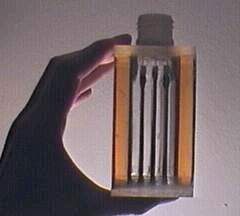
The finished product!
 When connected to my fully charged 12v battery (which actually
puts out more like 12.5v at these currents) I measured a current
of 9.4 amps running through the unit. This means that I am
generating 430 mL of gas mixture (67% hydrogen, 33% oxygen) per
minute. In addition, the unit is generating about 60 watts of
heat in steady-state operation. The conversion factor between
amps and mL-gas-per-min is 45.6 for a four-cell unit. Incidently,
9.4 amps is a lot of current, so it is important that the
electrical connections be rated to take that kind of current. I
use a household-style light switch between the battery and my
unit so I can switch the current flow on and off in a hurry.
When connected to my fully charged 12v battery (which actually
puts out more like 12.5v at these currents) I measured a current
of 9.4 amps running through the unit. This means that I am
generating 430 mL of gas mixture (67% hydrogen, 33% oxygen) per
minute. In addition, the unit is generating about 60 watts of
heat in steady-state operation. The conversion factor between
amps and mL-gas-per-min is 45.6 for a four-cell unit. Incidently,
9.4 amps is a lot of current, so it is important that the
electrical connections be rated to take that kind of current. I
use a household-style light switch between the battery and my
unit so I can switch the current flow on and off in a hurry.
Postscript, 2010
The bulk of this document was written in October 2000. This
section is written in 2010. After having used my second-generation
electrolysis cell several times I discovered a problem in
its design which I remedied in a successive design
iteration.
Basically this is the problem: if I ran the unit for more than
a couple minutes it heats up due to resistive heating (basically,
about half the power applied to the unit is converted to heat;
the other half causes the electrolysis). Upon heating, the steel
electrode plates and the acrylic and epoxy all expand, but
unfortunately in different amounts. This mismatch in expansion
caused stresses which opened a hairline crack where the
metal tabs protrude from the enclosure. I noticed a small
amount of electrolyte seaping through this opening.
What is the solution? When I made a third-generation unit, I had the tabs
protrude from the enclosure near the top, above the liquid line.
This way if an opening develops the electrolyte will not leak out.
Next, I only have two tabs protrude--only those for the
outer-most plates across which the 12-13v is applied. Third, I tried not to
use the steel electrodes as such an integral part of the structure,
that is, I had them sort of loosely fit within the
grooves on the interrior of the enclosure, which is still constructed of acrylic sheets, now on all 6 sides. I more carefully
sealed the opening in the acrylic where the two steel tabs protrude. Fourth, I made the plates about twice as large in area and use six stainless steel plates (instead of 5) making 5 cells in series (instead of 4). This means there will be less voltage per cell, but the larger size allows the plates to operate more efficiently (less current density). The net result is at least 25% more gas for the same electrical power input. Fifth, for safety I cut the concentration of electrolyte in half. And I found a source of KOH instead of NaOH to use becuase KOH has a bit more conductivity, again making things more efficient so there is less heating during operation.
All contents copyright ©2000-2017 Dean Wheeler
Disclaimer: This document is for informational
purposes only and is provided free of charge, obligations, and liability to
the author. The author expressly disclaims any warranties
on the accuracy and fitness of the information provided on this
page for any particular purpose.