|
Student will |
|
- Become familiar with the Seiko D-Tran teach pendant and its function keys.
- Learn how to move the robot using the controls on the teach pendant.
- Learn how to teach and store target points for the robot to move to
.
|
Prerequisites Materials
No prerequisites required. Pen and paper to record observations.
Terminology Teach Pendant -
Operator interface device used to teach/save robot configurations and program simple instructions.Tool Control Frame -
This is the coordinate frame of the robot tool. This is also abbreviated as the TCF. Joint Interpolated Motion
- Motion where the joint taking the longest time to make the joint change governs the motion and the other joints are slowed in proportion so that all joints accomplish their joint changes simultaneously with the slowest joint.
Linear Interpolated Motion - Motion where the tool control frame moves along a linear path from one configuration to another in Cartesian (physical) space. Teach Pendant Commands Used in this Lab -
MOTOR ON - This turns the robot motors on. MOTOR OFF - This turns the robot motors off. MCAL - This calibrates the robot axes. This causes the robot to find the position of the robot axes with sensors at the
center of the motion of each axis. SFREE - This allows you to move the robot axes freely. SLOCK - This places the robot axes back under robot control. P* - This allows you to define a configuration for the robot.
JOG MODE - This allows you to continuous and step jog modes for the robot. JUMP - This moves the robot to a new position by first raising the Z axis, then moving horizontally above the new position, and then lowering
the Z axis to arrive at the new position. GO - This moves the robot to a new position with joint interpolated motion. Introduction
The teach pendant can be used to teach the robot configurations of the robot
joints. Then the teach pendant can be used to move between those configurations in either joint interpolated moves, or linear interpolated moves. The XM3000 robots in the lab are XYZ robots, meaning that
they move in X, Y, Z directions. Because of this, linear interpolated moves travel through the same path as joint interpolated moves. However, linear interpolated motion is still necessary to allow the robot
to move other paths that are defined in Cartesian (physical) space, such as circles and ellipses. Cartesian moves can be specified in the world frame, in which the directions correspond to the directions of the
robot axes (for example, the X direction is in the same direction that the robot's X axis moves), or they can be specified relative to the tool. Using Spel for Windows, the tool coordinate system can be defined
and Cartesian moves can be made in that frame. This can be useful when inserting the tool into a hole. After aligning the tool, a linear move in the direction of the tool axis could be specified.The robot
moves at a slower speed when it is being controlled by the teach pendant than it normallly could. This is because the robot is moving with a person nearby when the teach pendant is in use. To reduce the
chance of harm to the operator, the robot moves slower when the teach pendant is used to control the robot. Procedures
|
On-Line:
- This lab requires the use of the number 1 Robot (on the west, or left side of the room) in the EAAL in CTB 145.
- This lab must be run on the EAALMASTER computer.
- This lab also requires the use of the
 Teach Pendant
module, which is also found in the EAAL.
|
Net Control: Not available for this lab. |
| |
Task 1: Turn on the Robot
|
Locate the controller for the robot on the west side of the lab.
 Make sure that the robot controller is on (follow link for instructions)
.
Make sure that the robot controller is on (follow link for instructions)
.
|
|
Task 2: Prepare the Software
|
- Open SPEL for Windows on the EAALMASTER NT workstation. The EAALMASTER workstation has a nameplate on it to identify it. To open SPEL for Windows, press the Start button in the
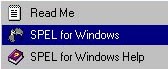 lower-left corner of
the Windows screen, then press Programs, SPEL for Windows, and then select the SPEL for Windows program. Select on the graphic for an image of the correct Start Menu selections. lower-left corner of
the Windows screen, then press Programs, SPEL for Windows, and then select the SPEL for Windows program. Select on the graphic for an image of the correct Start Menu selections.
- On the robot, make sure that the Auto/Teach
 switch is set to Auto (This switch is located beneath the framework, near the tool changing station, on the right of the robot). If the switch
is not set to Auto, then SPEL cannot connect to robot. switch is set to Auto (This switch is located beneath the framework, near the tool changing station, on the right of the robot). If the switch
is not set to Auto, then SPEL cannot connect to robot.
- In SPEL for Windows, press the Setup menu button and select PC to Robot Communications. Select the following options if they are not already selected:
Robot Number - Robot 1
PC RS232 Port - Comm 1
Baud Rate - 19200
Robot Controller Port - #20
Then close the window by clicking in the very upper-left corner and then selecting Close. Do NOT exit by pressing OK or TEST. This will
attempt to reconfigure the robot's serial ports. If OK or TEST are accidentaly pressed, press Cancel in the next window.
- On the SPEL for Windows menu toolbar, press
 the "Robot Control Panel" icon. the "Robot Control Panel" icon.
- When the Robot Control Panel comes up, press the "Pendant" button found on the bottom right corner of the window.
 A window will appear that instructs you to connect the teach pendant to the teach port and to switch the controller to Teach mode. The next
steps show you how to complete this process. If a different window appears, press cancel and select "Pendant" again. If it again does not ask you to connect to the teach pendant as stated
above, then contact the teaching assistant. A window will appear that instructs you to connect the teach pendant to the teach port and to switch the controller to Teach mode. The next
steps show you how to complete this process. If a different window appears, press cancel and select "Pendant" again. If it again does not ask you to connect to the teach pendant as stated
above, then contact the teaching assistant.
|
- Go over to the controller to plug in the teach pendant. If the teach pendant cable is plugged into the TEACH port of the XM1 robot (west robot), then go to the next step. If the teach pendant is not already
plugged into the TEACH port, the teach pendant must be plugged in. If there is something other than the teach pendant cable plugged into the
 TEACH port, remove it and leave it hanging on its chain. In the TEACH port,
place the RS-232C 25-pin cable belonging to the teach pendant. While doing this, keep the white button (emergency stop cancel switch) pressed down so you won't have to turn the
robot on and off after the teach pendant has been connected. TEACH port, remove it and leave it hanging on its chain. In the TEACH port,
place the RS-232C 25-pin cable belonging to the teach pendant. While doing this, keep the white button (emergency stop cancel switch) pressed down so you won't have to turn the
robot on and off after the teach pendant has been connected.
- Verify that the emergency stop has not been activated. This is done by checking to see if there is a red light under the words 'Emergency stop' on the robot controller. If
there is a red light, then turn the controller off, wait about 20 seconds, and then turn it back on.
- To enable the teach pendant, set the Auto/Teach switch to the down, or Teach, position. This switch is located beneath the framework, near the tool changing station, on the right of the robot.
- Press the "OK" button in the SPEL for Windows program at the prompt.
- Verify that the teach pendant is functional by checking the display in the SPEL for Windows program on the computer. A window should appear with the words "Pendant has control".
On the teach pendant read-out there should be
 numbers and a command (CMD) prompt. Press the numbers and a command (CMD) prompt. Press the ENTER button, if prompted.
- If SPEL does not show "Pendant has control", or the teach pendant reads "TEACHING PENDANT IS NOT VALID", then repeat steps 2 through 9.
|
Task 3: The Teach Pendant
|
- Look at the teach pendant (the control box) and familiarize yourself with the buttons. Don't press anything yet, but just look at them. There is a keypad area, an LCD display, the enable button on
the left side, and the shift button on the right side.
|
- Press "
F1", which
is a shortcut key for the "MOTOR ON" command. You can see that "MOTOR ON" is now written next to the "CMD:" in the command window Press ENTER. The motor will now turn on.
|
Task 4: The Teach Pendant Controls
|
- Note the buttons on each side of the teach pendant. On the left side of the teach pendant is the
ENABLE button, and on the right side of the teach pendant is the SHIFT button. Press "
F3" and then press
the ENABLE button. 
- While holding the ENABLE button down, press the
ENTER button. "F3" represents a short cut to the "MCAL" command that calibrates the robot upon start up. Once the robot stops moving, you
can let go of the enable button. Without depressing the ENABLE button, you cannot use any of the commands that cause the robot to move.
|
- The
SHIFT
button is on the right side of the teach pendant.
- Press the
SHIFT
button and while holding it down, press the SFREE button. On the command screen, to the right of "CMD: " you will see the command SFREE typed in. Press the NUM button and then
type in "1, 2, 3, 4
" on the numerical keys (the comma is at the bottom and requires pressing the SHIFT button at the same time) and then press ENTER. In our case, joint 1 is X, joint 2 is Y, joint 3 is Z,
and joint 4 is U or the rotating joint.
- Press CLR (clear) or BS (backspace) on the teach pendant to delete the command if you make a mistake
|
Task 5: Teaching the Robot a Configuration.
|
- Now you can move the X and Y axes to any position you want. In order to move the Z axis up or down, you must press the white button (brake release)
 on top of the Y axis motor. on top of the Y axis motor.
- Move the Z axis manually to some arbitrary height. Then turn the U axis no more than 90 degrees to some arbitrary rotation.
- Press the
P*
button. In the prompt, at the command line, you should see: "P_=P*". Simply type in "0" and press ENTER.
- Repeat the process for moving the axes and pressing
P* again, but typing 0 after pressing the P*
button.
- Press the
SLOCK
button. (The same as the SFREE button except without the SHIFT key.) Press the ENTER button and the motor will come back on.
|
- Now you can use the JOG feature to move the robot, instead of manually moving it. Simply press the
+/- buttons next to the joint you want to use, and the robot will move (while holding the ENABLE
button, of course). By pressing the JOG MODE button, you can select between moving in small, medium, or large step, or continuous modes. Move the robot to two more positions, storing them by pressing P* followed by a 2
for the next position, and P* followed by a 3 for the last position.
- You have now taught the robot 4 different configurations: P0, P1, P2, and P3. (What you have actually done is taught the controller a set of joint values that corresponds to those selected configurations).
|
Task 6: Testing the Points
|
- Press the
JUMP
button and type 0
. Then press and continue to hold the ENABLE button while pressing the ENTER
button. The robot will perform a non-interpolated move from P3 to P0.
- Now press the
GO
button. This is the JUMP button while holding down the SHIFT button simultaneously. This will bring up the GO command. Type in 3, hold down the ENABLE button, and press
ENTER.
- Notice the difference between the JUMP command and the GO command. In the JUMP command, each of the axes took turns, while in the GO command, the axes all started together and ended together. The GO
command is an example of joint interpolation. Although the course of the TCF from point P0 to point P3 looked like a straight line, the GO command does not always generate one. The MOVE command generates a
linear path but will not be demonstrated with the teach pendant.
|
- Use the JUMP and GO commands to move the robot to P0 through P3 in any order. Do this by pressing the
GO or JUMP buttons followed by the number of the position to move to. To execute the move, press the ENABLE button and press
ENTER
, as done before.
- After you have finished moving the robot, press "
F2", and then press ENTER
to turn the robot motors off. Then press the "Done" button in the Spel for Windows program on the EAALMASTER computer. You will be told to switch to AUTO mode. Do this by switching the small Auto/Teach switch on the right of the robot to AUTO. If the Spel for Windows program asks if you want to save the 'MAINGRP.PNT' file, press "No". Press "Close" in the Robot Control Panel.
Close the Spel for Windows program by pressing the File menu button and then pressing Exit.
- Remember: switch the small Auto/Teach switch to AUTO. Leave everyting else as is. Take the quiz. Good Luck.
|
Assessment You
can now take the on-line quiz. The results of this quiz will be automatically forwarded to an EAAL TA. In addition, you will receive immediate notification of your correct and incorrect responses for the mutiple choice
questions. The narrative questions will be evaluated by the TA and the response returned to you by EMAIL.You are free to perform this lab again if you are not yet prepared for the on-line quiz.
On-Line Quiz |
|
